1931
CHEVROLET ADJUSTMENTS OF STEERING GEAR
To Remove Sector Shaft End Play
The following operations are necessary to remove endplay in the sector shaft:
1. Loosen Nut “A” (motor side of gear).
2. Turn screw “B” right hand, to remove and play from sector shaft.
3. Tighten lock Nut “A”
securely. (See Fig. 118).
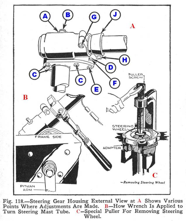
To Remove Worm Shaft End
Play
Worm shaft endplay is evidenced by up and down movement of the steering wheel. It is compensated for as follows:
1. Remove air cleaner.
2. Disconnect horn wire.
3. Loosen “U” bolt nuts at instrument panel.
4. Loosen housing clamp bolt “G.” (Fig. 118).
5. See that clamp bolt “H” is pulled up as tightly as possible.
6. Rotate mast jacket to the right by gripping clamp “J” with a wrench as far as possible without stiffening the action of the steering wheel while turning through its entire range. The mast jacket must be turned toward the right only, as the adjusting nut must be in positive contact with the bearing when the adjustment is complete. (See Fig. 118 - B).
7. Tighten housing bolt “G.”
8. Loosen clamp bolt “H.”
9. Rotate mast jacket until horn wire is at bottom.
10. Tighten clamp bolt “H.”
11. Tighten “U” nuts at Instrument Panel.
12. Connect horn wire.
13. Replace air cleaner.
To Remove
Backlash Between Worm and Sector.
Too much backlash between the worm and sector is evidenced by too much lost motion of the hand wheel. To correct this condition proceed as follows:

WORM GEAR ON ITS SHAFT
1. Locate wheels exactly in straight ahead position. This is very important.
2. Disconnect drag link from pitman arm and move arm back and forth to determine the amount of backlash.
3. Loosen cover stud nuts “C” ¼ turn only. (Fig 118 - A).
4. Loosen nut “D” ½ turn only.
5. With one wrench on eccentric bolt “E” and one on eccentric sleeve “F” turn bolt “E” and sleeve ”F” in opposite directions in gradual stages, noting results by moving pitman arm at each step and using care at the last stage to turn bolt “E” and sleeve “F” just enough to remove backlash and no further. If bolt “E” and sleeve “F” are turned more than necessary, damage to gear will result. In most cases 1/8 turn of bolt “E” and eccentric sleeve “F” should be sufficient.
6. Tighten nuts “C” and “D” securely and connect drag link.
7. Check backlash at steering wheel. In straight-ahead position, the wheel should not be tight but should have no backlash. When properly adjusted, the steering gear will be without backlash in straight ahead position only.
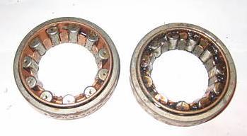
BEARINGS
Adjustment of Steering Linkage
One of the most important adjustments on the Chevrolet cars and trucks is the proper adjustment of the steering connecting rod and front axel tie rod and the correct alignment of the front wheels. All these adjustments, together with proper tire pressure and lubrication, tend to make steering easy, prevent unnecessary tire wear, eliminate front wheel shimmy and insures the safety of the car and occupants at any speed.
Steering
Connecting Rod.
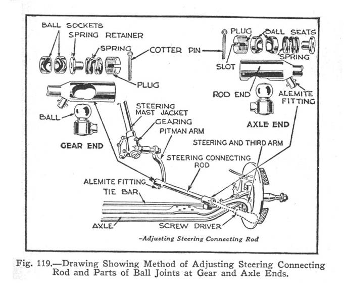
The steering connecting rod, commonly called the drag link, which connects the steering and third arm on the front axel to the pitman arm, is of conventional design.
Refer to Fig. 119, and note how parts are assembled. On the axel end the spring and spacer are assembled between the rod end and the ball seat. On the steering gear end the spring and spacer are assembled between the ball seat and end plug. This is very important as the springs assembled in this manner relieve road shock from the steering gear in both directions.
To properly adjust this steering
connecting rod:
1. Remove cotter pins.
2. Screw plugs in tight and back off to first cotter pin hole.
3. Insert and clinch cotter pins.
4. Lubricate both ends of tie rod.
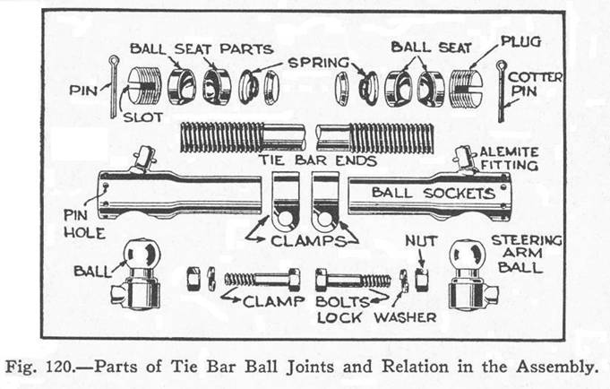
Front Axel Tie Rod
The front axel tie rod is of the ball,
seat and spring type, similar to the steering connecting rod construction. Refer to Fig. 120,
and note how parts are assembled. The
parts on both ends are assembled in the same manner. First the spring seat,
then the spring and ball seats, then ball and ball seat, and then the
plug. Ball seats should be assembled so
that notches line up with ball neck.
To properly adjust this front axel tie
rod, follow the same order of operations as given above for the steering
connecting rod.
Taking Lost Motion Out of
Steering Connection Rod.
Remove the cotter pin from the end of
the steering connecting rod (see Fig. 119). Remove screw plug and all internal
parts. Clean the rod ends and inside
parts with gasoline. Lubricate the ball
seat surfaces with heavy oil or light grease and reinstall.
With a screwdriver placed in the slot
in the screw plug, tighten until all parts are firmly and the spring compresses
solid, then back-off adjustment to the first cotter pin hole (Fig. 119). After this is done, all lost motion should be
removed from the ball joint. Be sure to
lock the cotter pin by clinching over, as a failure to do so may lead to a
serious accident. Use Alemite gun to
lubricate both tie rod ends.
Front Wheel Alignment
To make steering easy, it is required
that the front wheels show a “toe” in, that is, the distance between the inside
faces of the wheel felloes, measured at the height of the wheel hubs, should be
from 5/64” to 1/8” more at the rear than at the front. This causes the wheels to grip the road
better and allows the car to hold its course without undue action of the
steering mechanism, preventing undue tire wear.
By referring to Fig 122
the distance indicated by the line B –
i.e., between the inner sides of the wheel felloe at the rear of the front
wheels – should be from 5/64” to 1/8” greater than the distance indicated by
line A.
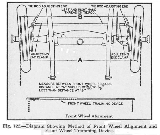
The best method of checking these
measurements is by the use of a front wheel-tramming device, as shown below the
diagram at Fig 122. Almost any good repair shop or tire station
is equipped with one of these devices and will check the alignment of the
wheels for you.
To decrease the line “A” loosen the adjusting
clamp screws at both ends of the tie rod and turn the tie rod to the
right. To increase this distance, turn
to the left.
After proper adjustment has been
secured, be absolutely certain to fasten both adjusting clamp screws firmly, ad
failure to do so may result in a serious accident to the car and occupants.
The tie rod ends are equipped with
Alemite fittings for lubrication and it is most important that the instructions
given on the Lubrication chart be followed.
These Alemite fittings are clearly shown at Fig 120.