|
|
|
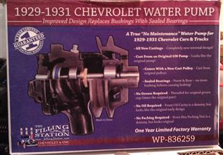 |
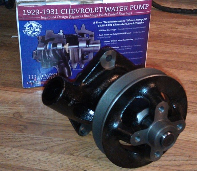
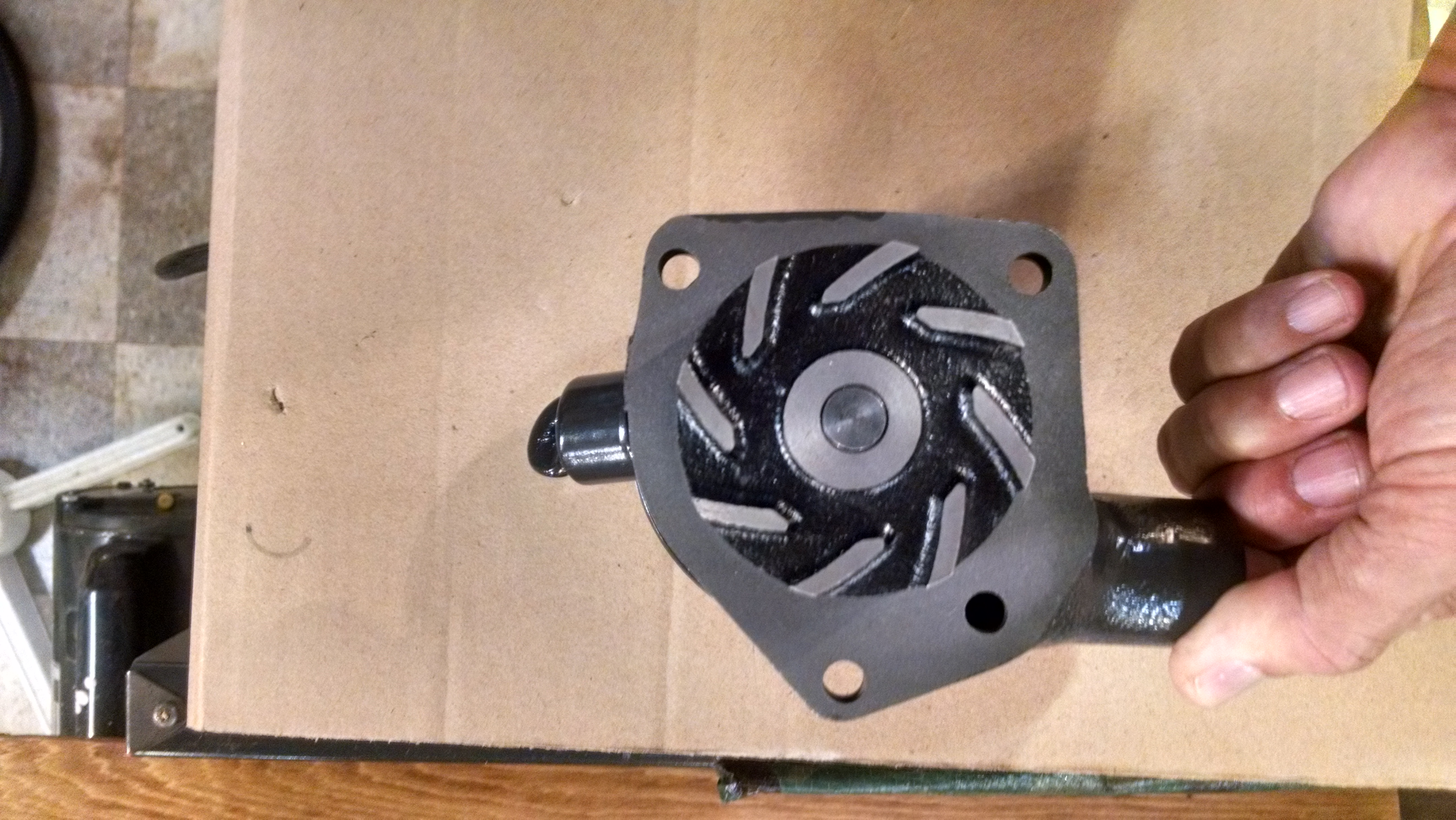
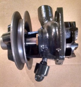
In 2014 The Filling Station (Lebanon, Oregon) came out with a new water pump for 1929-1931 Chevrolets. What makes this so significant is that these pumps don't have BUSHINGS in them any longer. Instead they are constructed with SEALED BEARINGS.
Additionally, this new design never needs to be greased. There is NO packing washer/rope required, and it never needs to be oiled. No maintenance is ever required again.
If you replace the fake zerk fitting with your old grease cup, then the pump LOOKS totally original. |
 |
|
|
|

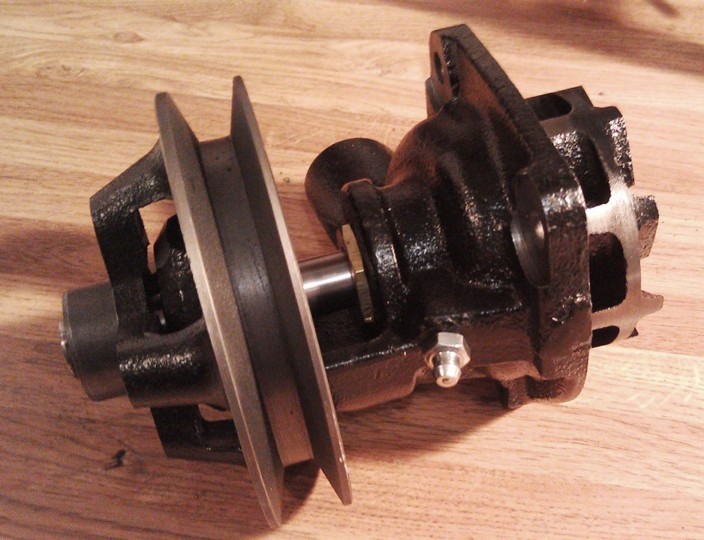
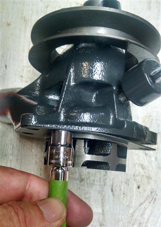
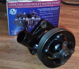
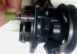
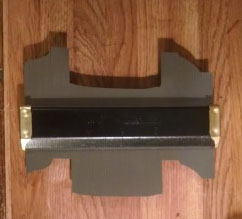
New pump out of the box with fake zerk fitting.
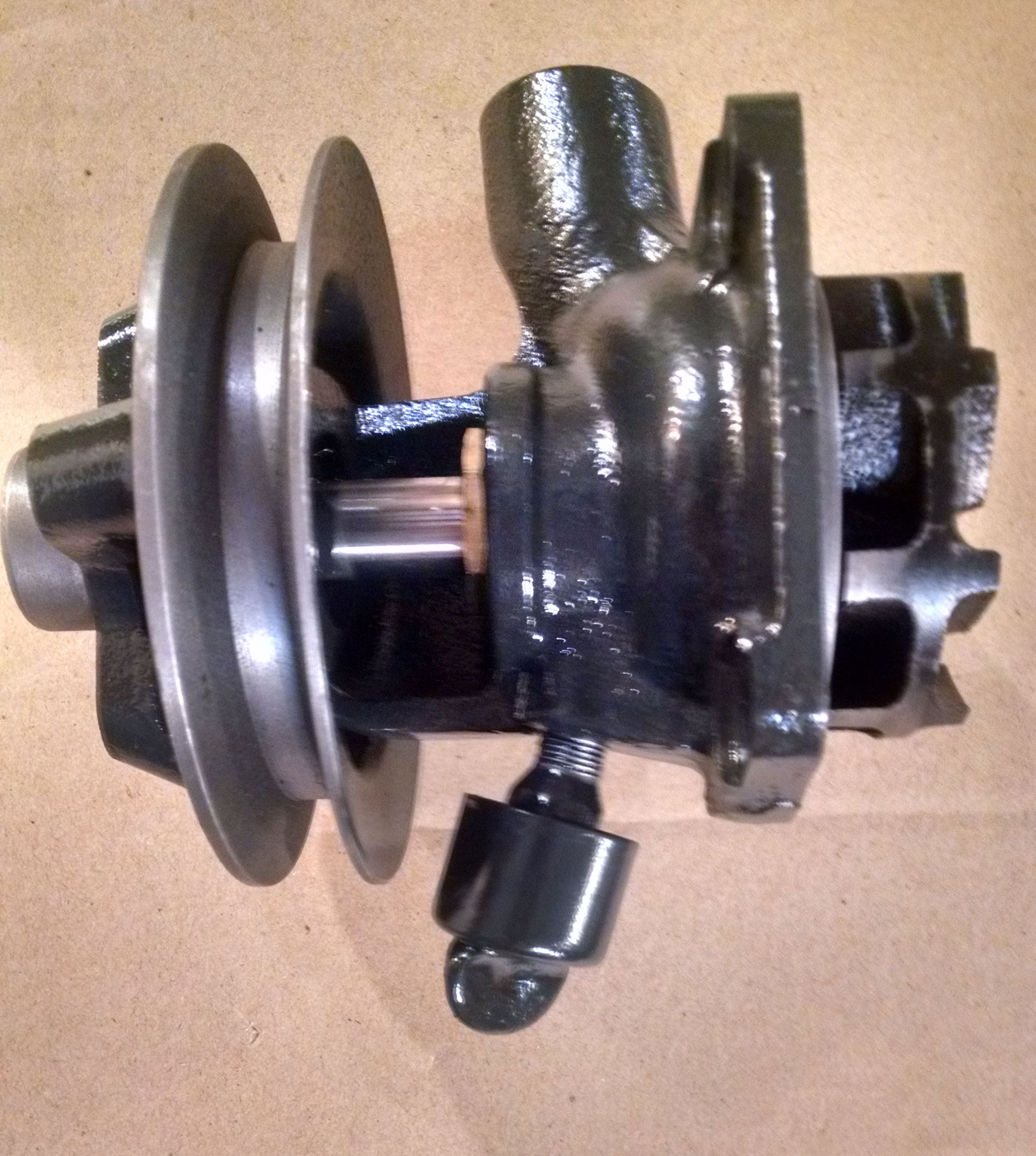
Here's the new pump with the original grease stem & cap attached. Just unscrew the zerk and put on your original grease stem and screw-on cap. Don't put any grease into the cap!! |
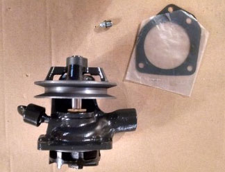
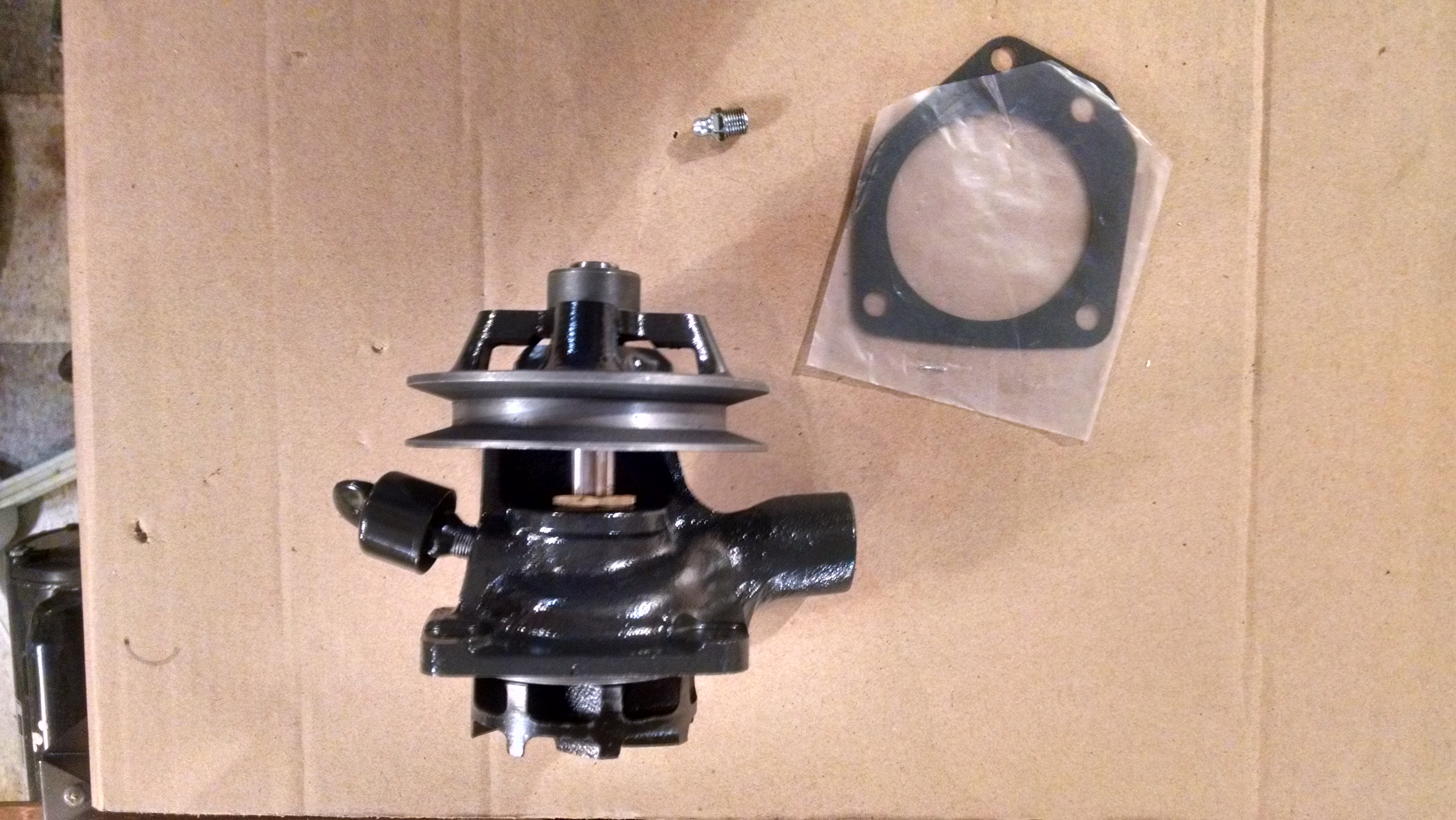
The new pump comes with a new gasket.
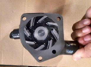
The new fin design is slightly more "aggressive" than the original. |

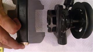
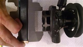
Removal of the old pump is very straight-forward. (1) Loosen the generator bracket. Rotate the generator slightly so that you can remove the fan belt. (2) Remove the fan blade. (3) Drain the radiator by opening the petcock at the bottom. (4) Remove one end of the radiator hose which leads to the water pump. No other hoses should be removed. (5) Remove the 3 bolts which hold the pump to the engine block. (6) Gently tap the pump on the side with a screwdriver or punch, slightly angled toward the front of the car (radiator). Do NOT try to pry it along the top where the pulley is. Otherwise you WILL break the pulley. (Ask me how I know.) |
|
|
|
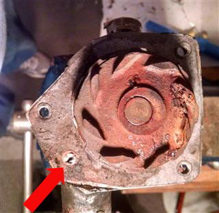
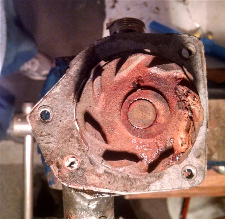
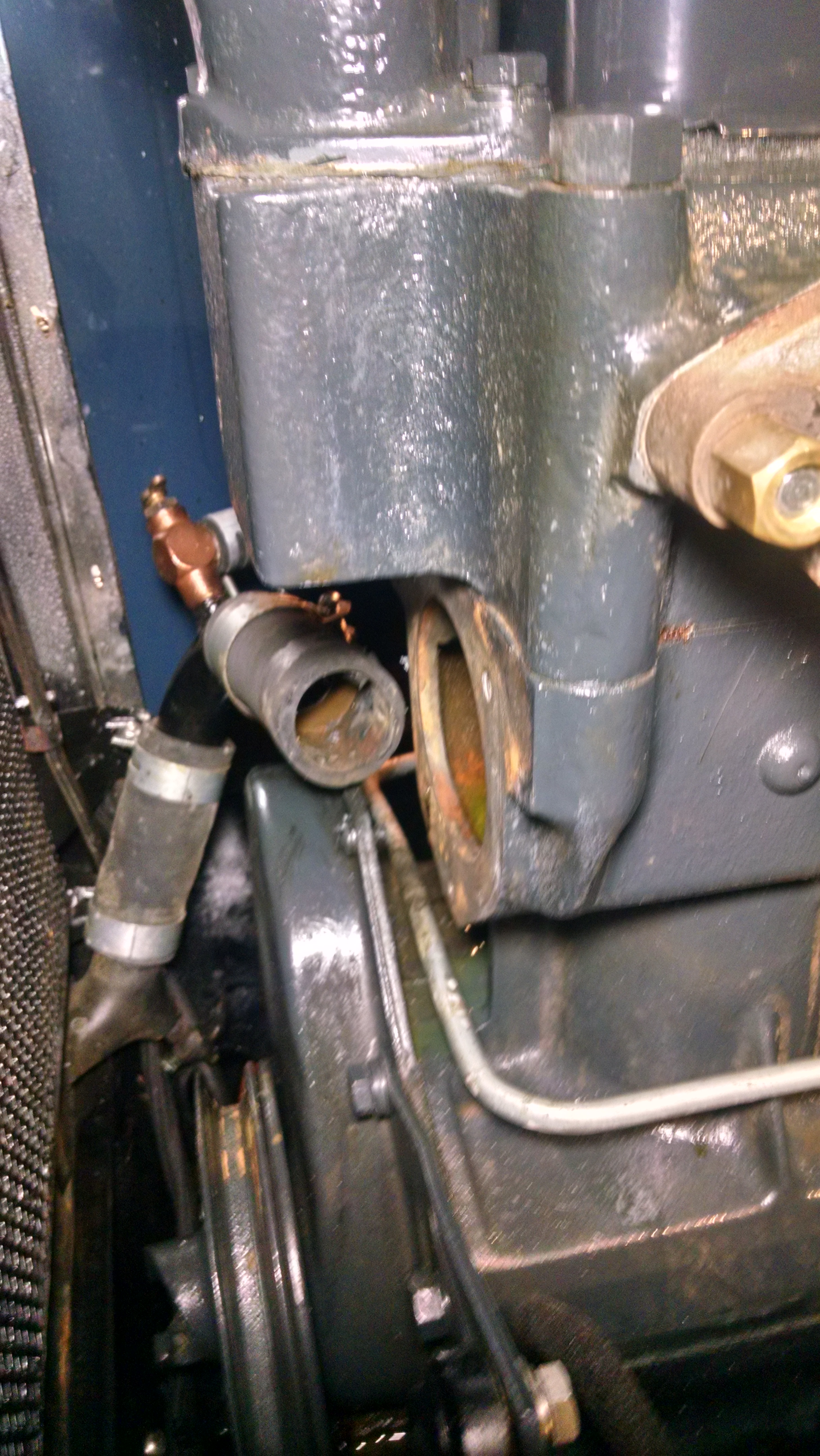
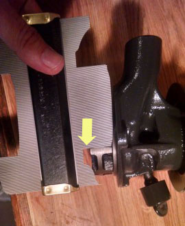
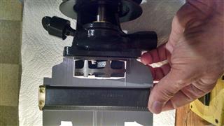
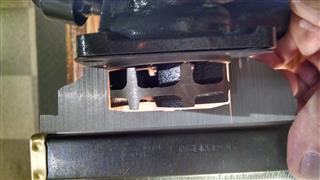
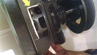
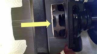
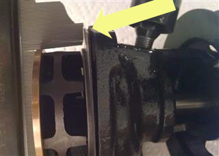
When I removed my pump, I found that the "relief" hole in the bottom of it was nearly closed due to excessive silicone which was used to seal the gasket. I believe that this hole allows water to be recycled back into the lower impeller area in order to prevent cavitation. |
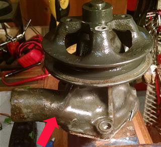
Here's the approximate location of this hole looking from the front. I think that it acts as a kind of "pressure relief" feedback loop. |
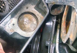
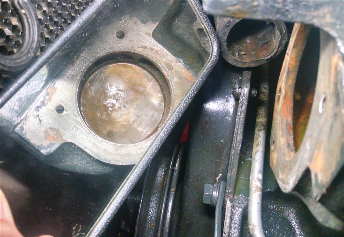
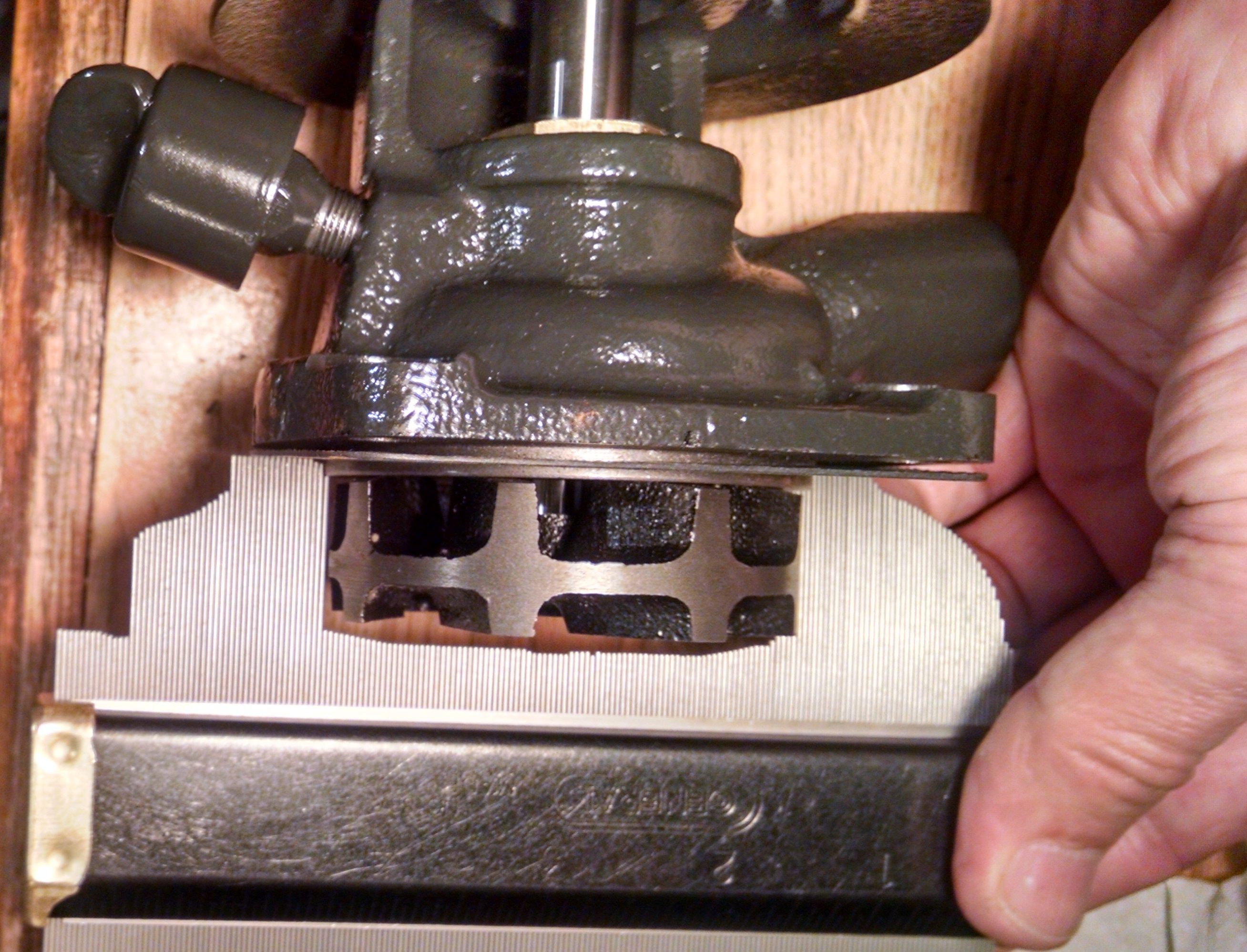
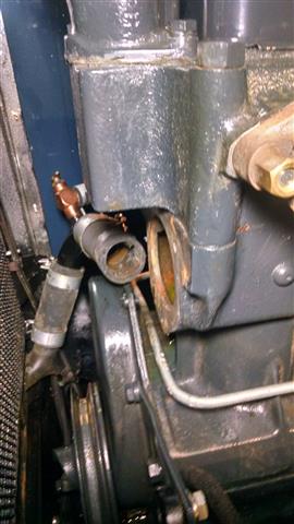
Looking in a mirror (left side) which is pointed towards the pump housing opening in the engine block (right side). You can't easily see that the center of the baffle plate is indented slightly. You can detect it by using your fingers to feel in there. But you don't really know "how much" it is indented without a way to measure it. |
|
|
|
| METHOD 1 - Poor man's measurement technique |
|
|
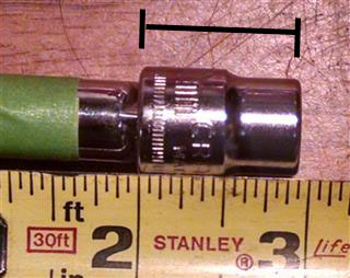 
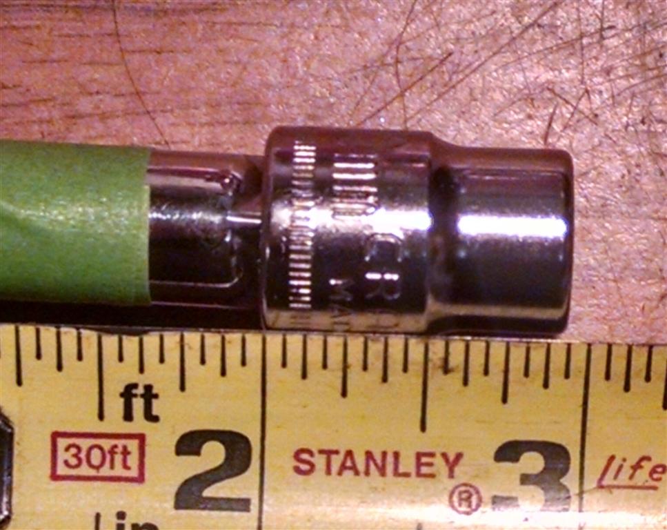
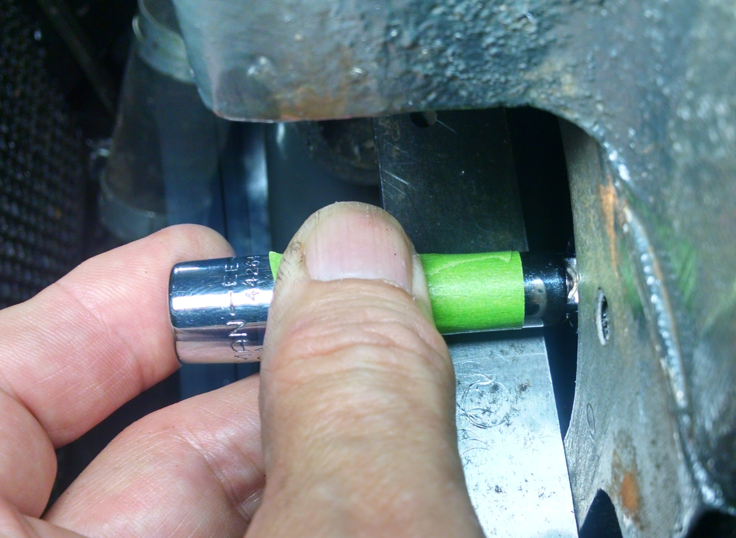
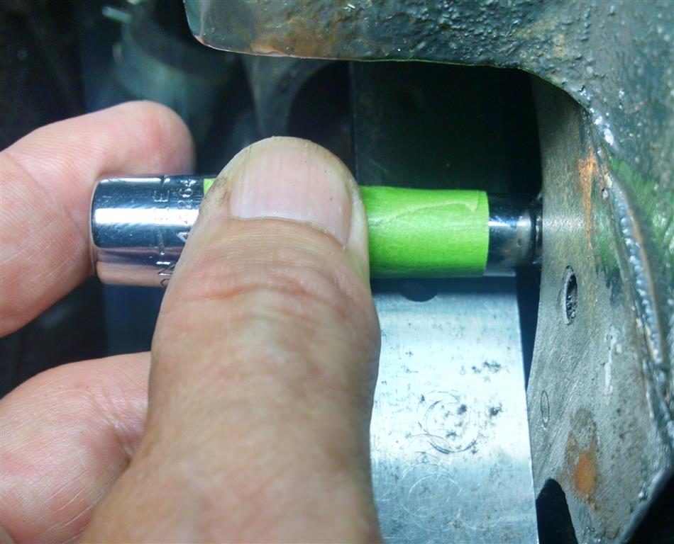
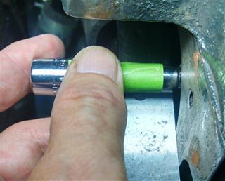
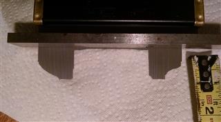
My solution to this was to find a socket (10mm) that was exactly the same size (in length) as the depth of the impeller was (15/16"). I placed it on a 3" extension so that I could hold it. Then I added a piece of tape to help visualize the depth. The tape began at 3/8" (or 6/16") from the bottom of the socket. This was purely an arbitrary distance that I chose. |
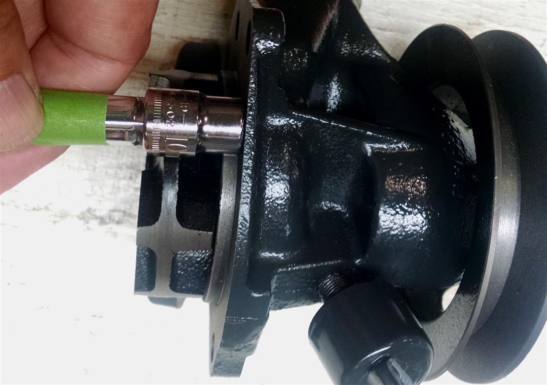
This shows that the socket that I used was the same length as the impeller was wide. Now I can use this to measure the depth of the opening in the engine block. |
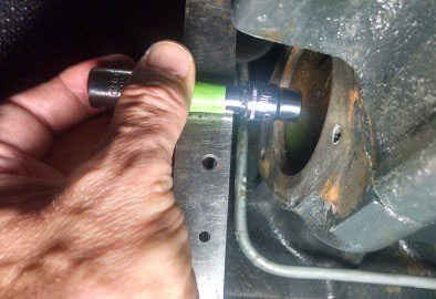
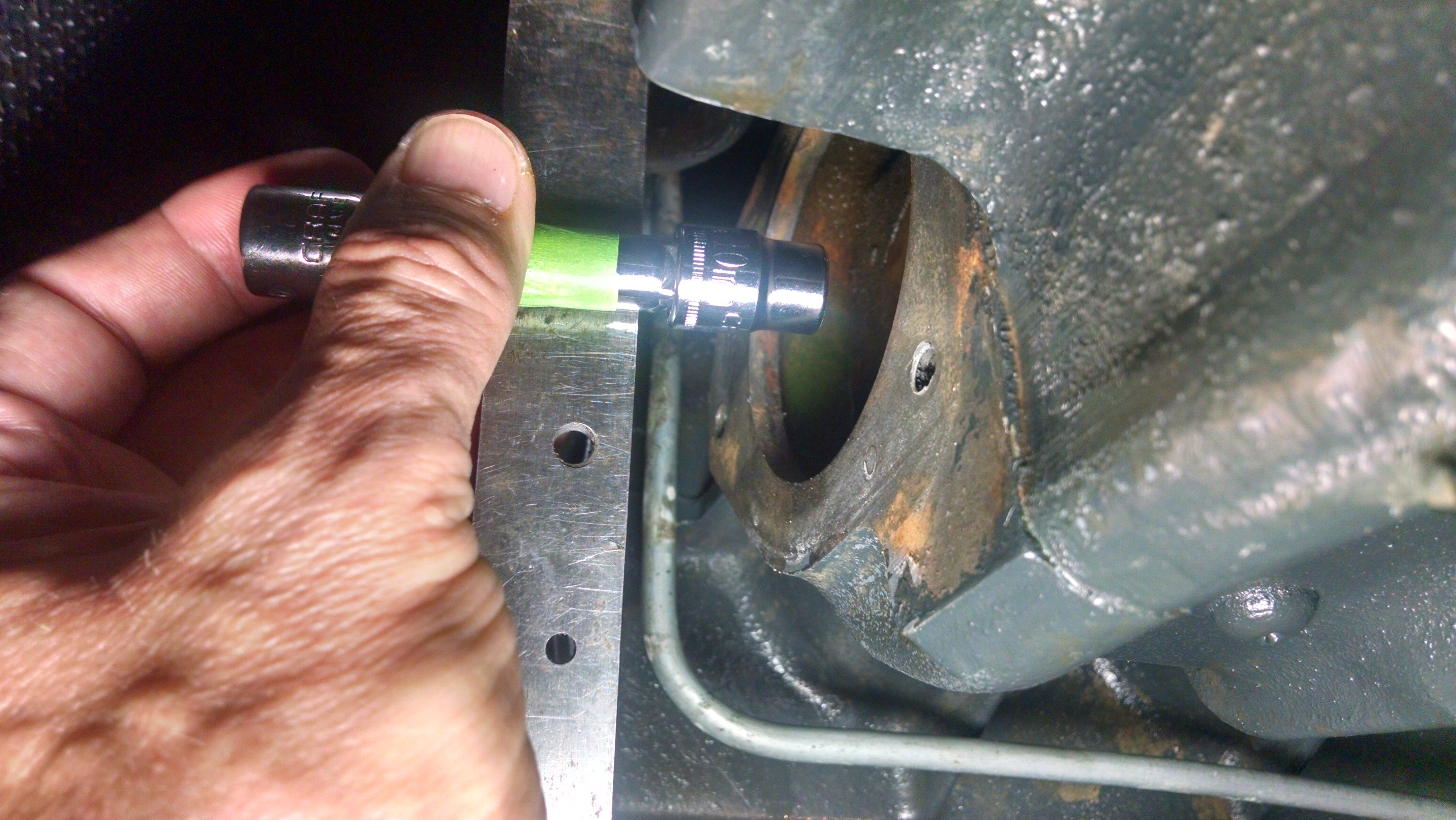
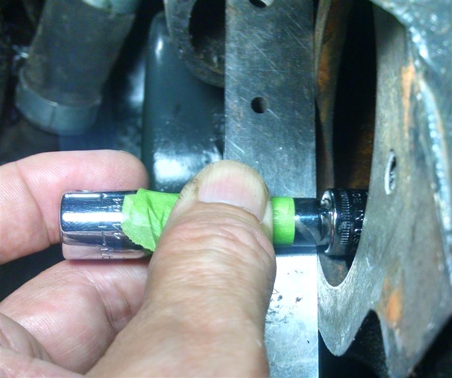
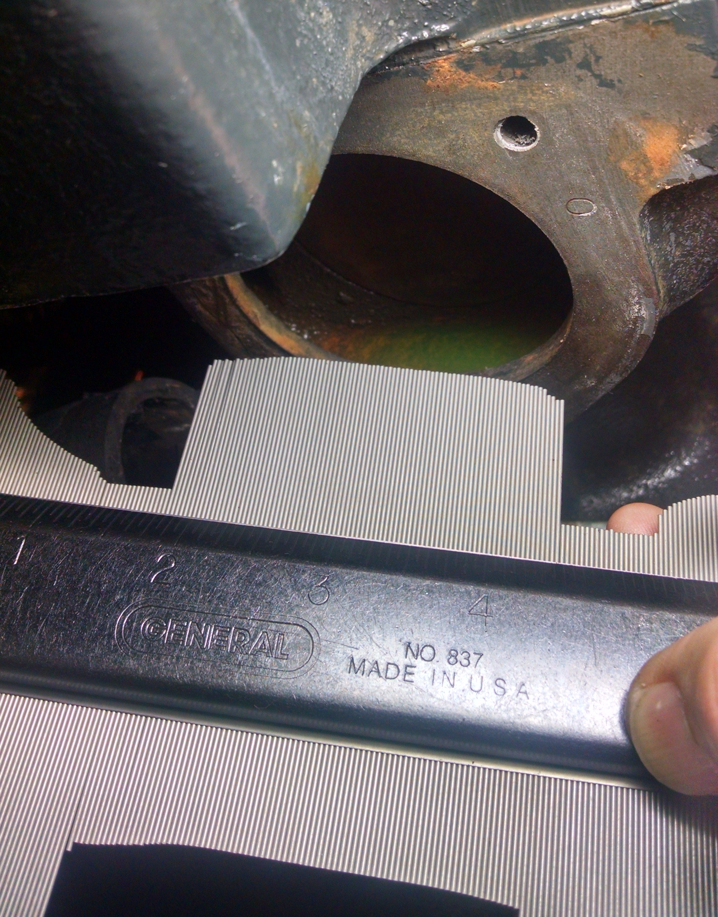
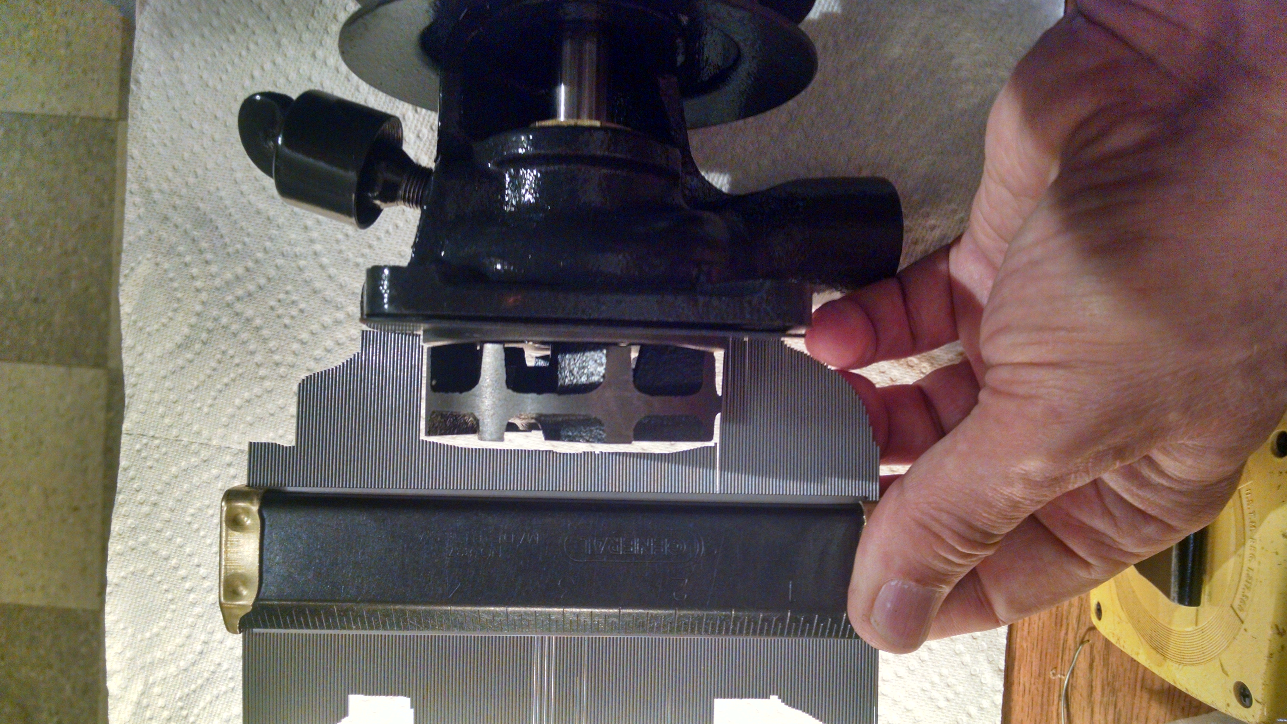
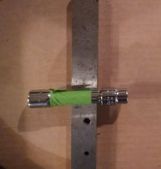
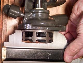
Then when I placed my "special tool" in the engine block, I used a metal straight edge across the water pump opening in order to hold it evenly so that I could measure how deep it went inside. |
| |
|
|
|
|
|
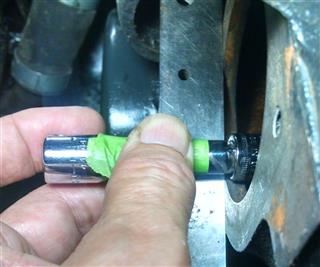
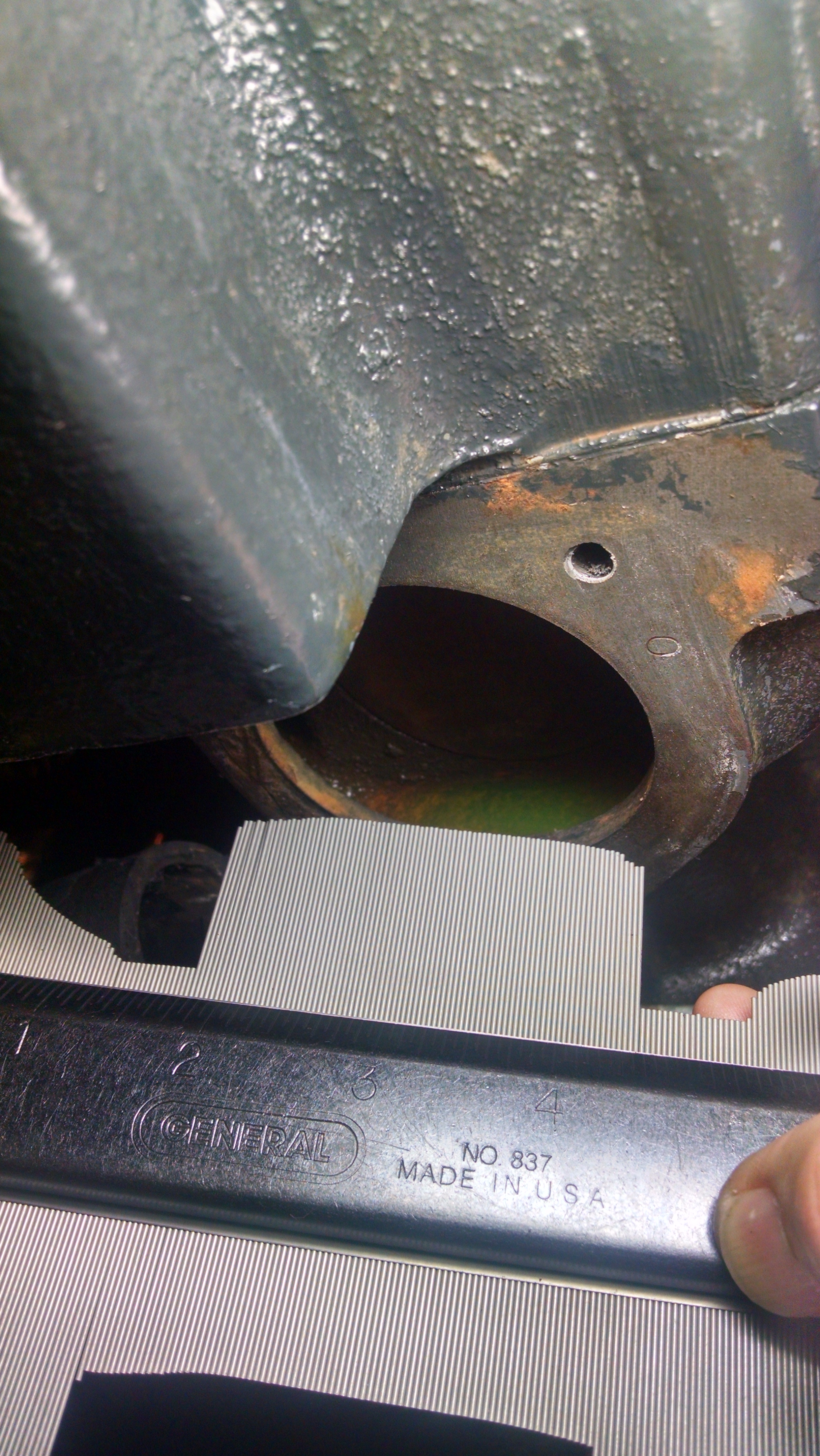
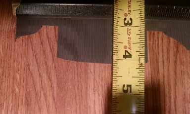
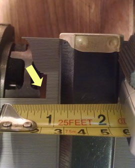
This measurement near the bottom, and at the outside edge, shows that the depth is nearly identical to the socket. (Due to the need to hold the camera away from the block, the parallax view slightly distorts the measurement in these photos.) |
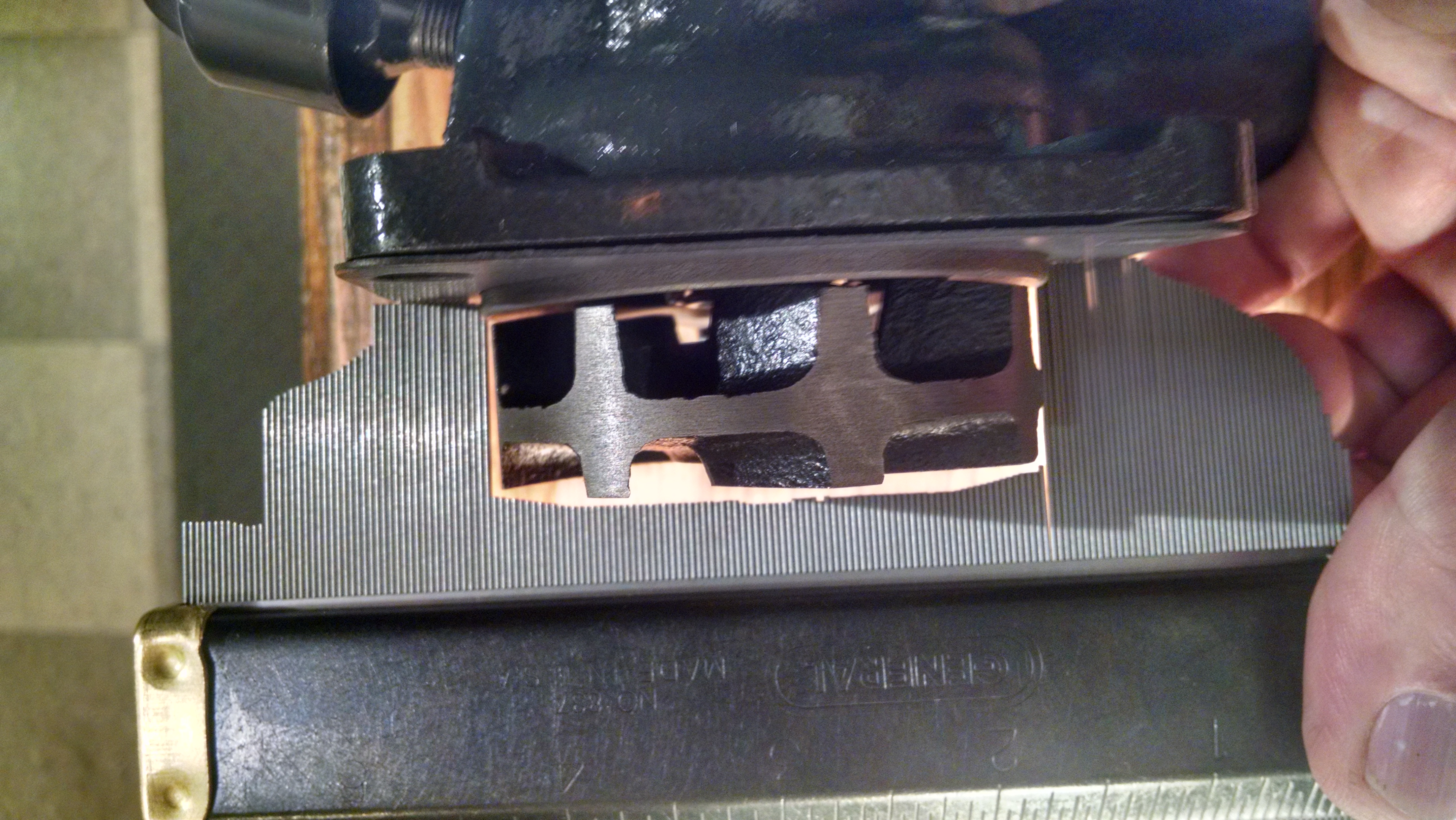
This measurement near the middle of the opening shows a reduced space to the green tape. Since the tape was at 6/16's from the socket, it appears that the baffle plate is indented about one half of that distance - or about 3/16 of an inch. That is TOO MUCH. This additional clearance between the impeller and the baffle plate allows too much room for the water to churn AROUND the impeller fins. The result will be a very ineffective pumping action. |
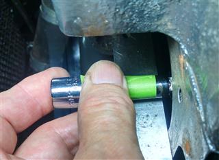
This measurement near the top of the opening shows that the depth is very close to the depth of the socket. So the only measurement that was excessive, was the one previous, near the middle of the baffle plate. |
|
|
|
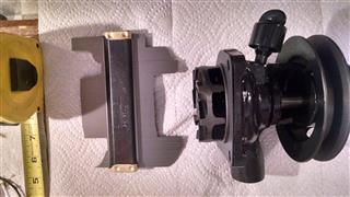
| Now that we've completed the measurements which show that the existing baffle plate has a nearly 3/16" indentation at the middle of it. . So my next step was to see how much additional space the GASKET was going to add to this dimension. As you can see to the right, it really isn't very significant. |
 |
|
|
|
|
| METHOD 2 - Buy a new tool measurement technique (!) |
|
|
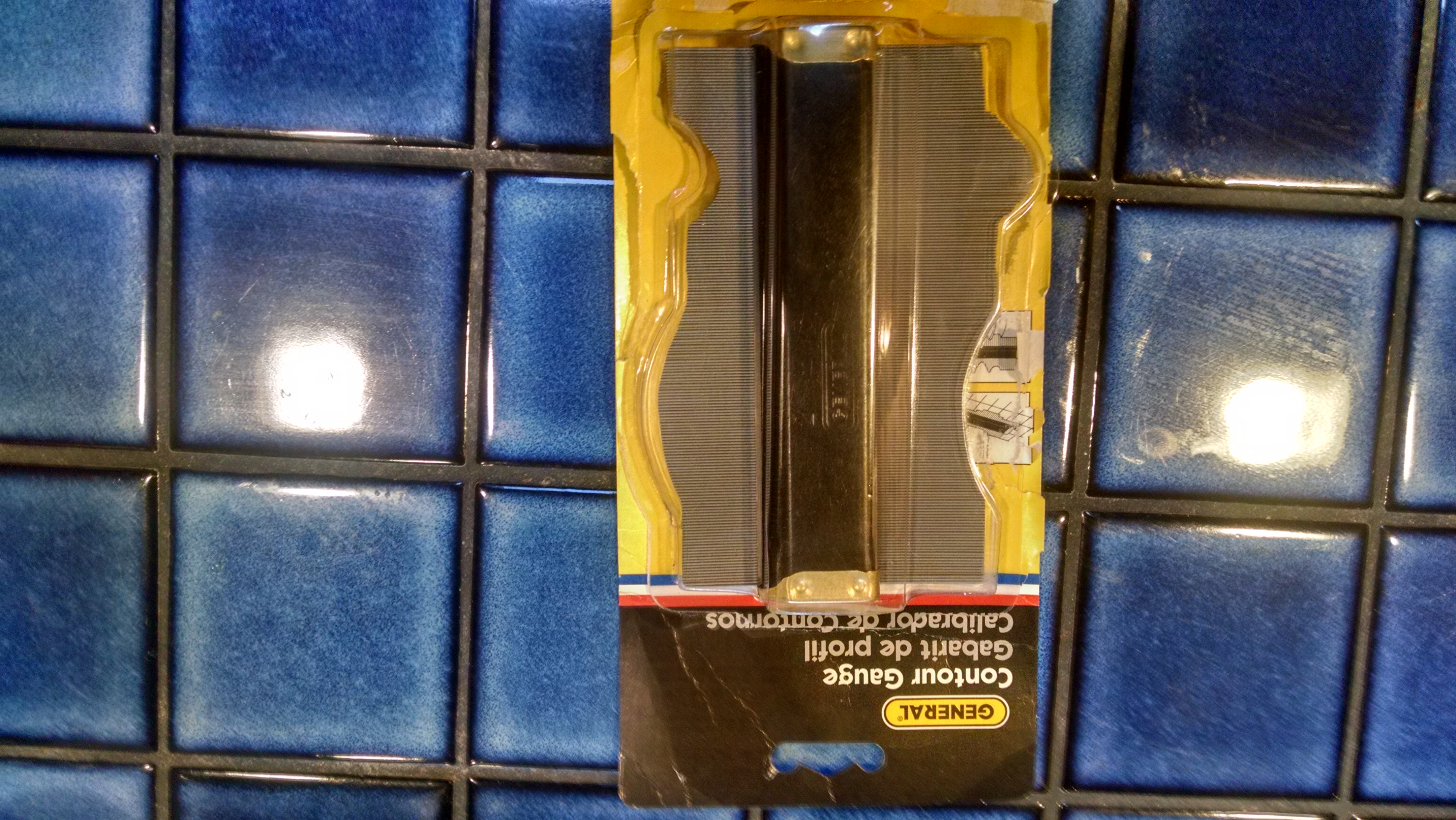
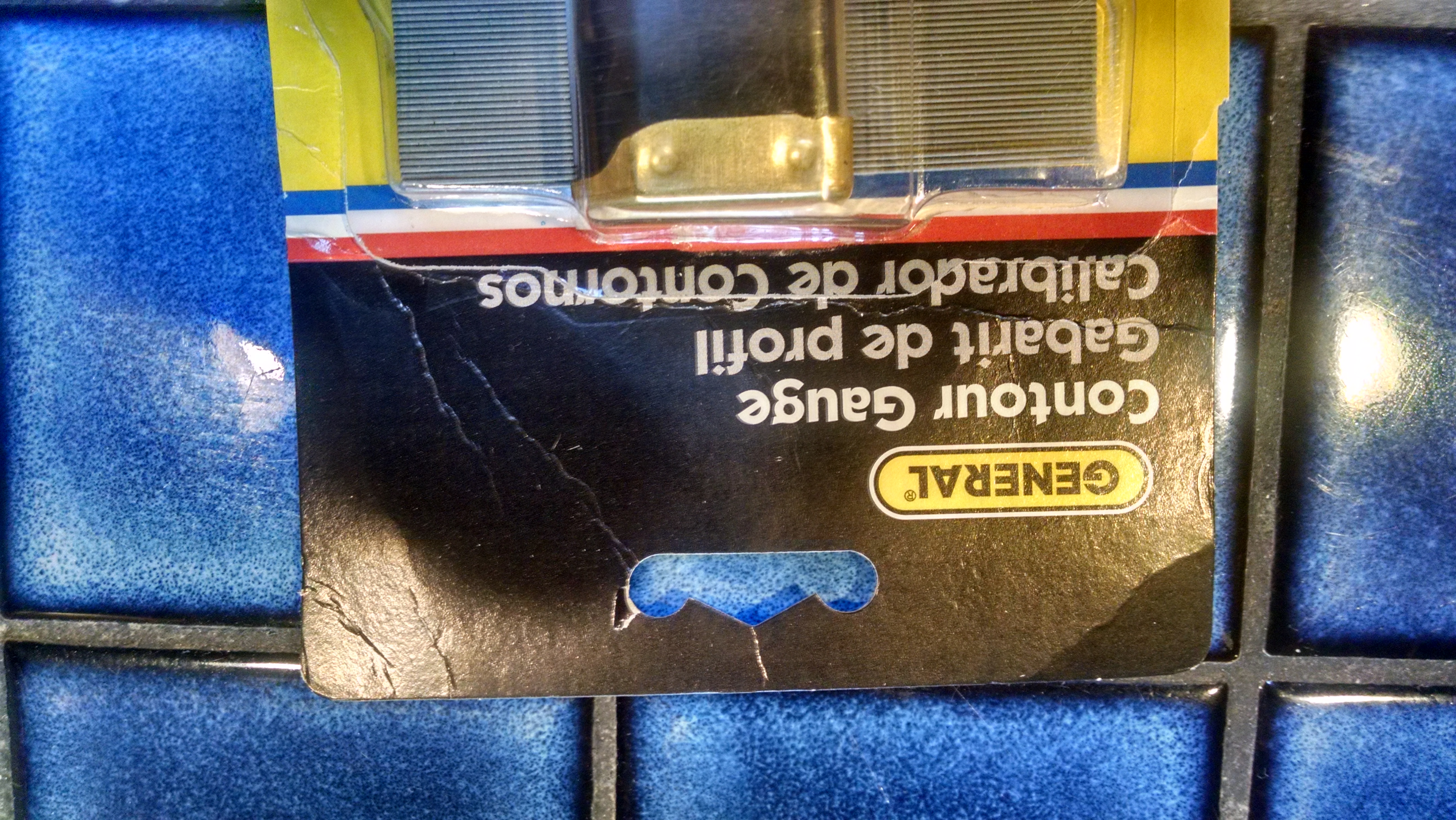
| I was sitting around last night contemplating how to better measure this space behind the impeller of the water pump. As I thought about the SHAPE, a bolt of lightening came to me. Define the shape and than measure THAT. Wow... but this was a tool that I didn't own. So I jumped on to Amazon.com and found this contour Gauge for $10 with Free shipping for me. I ordered it around 10 pm. By 3 pm the next day it was on my front porch. |
 |
 |
|
|
|
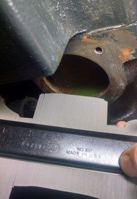
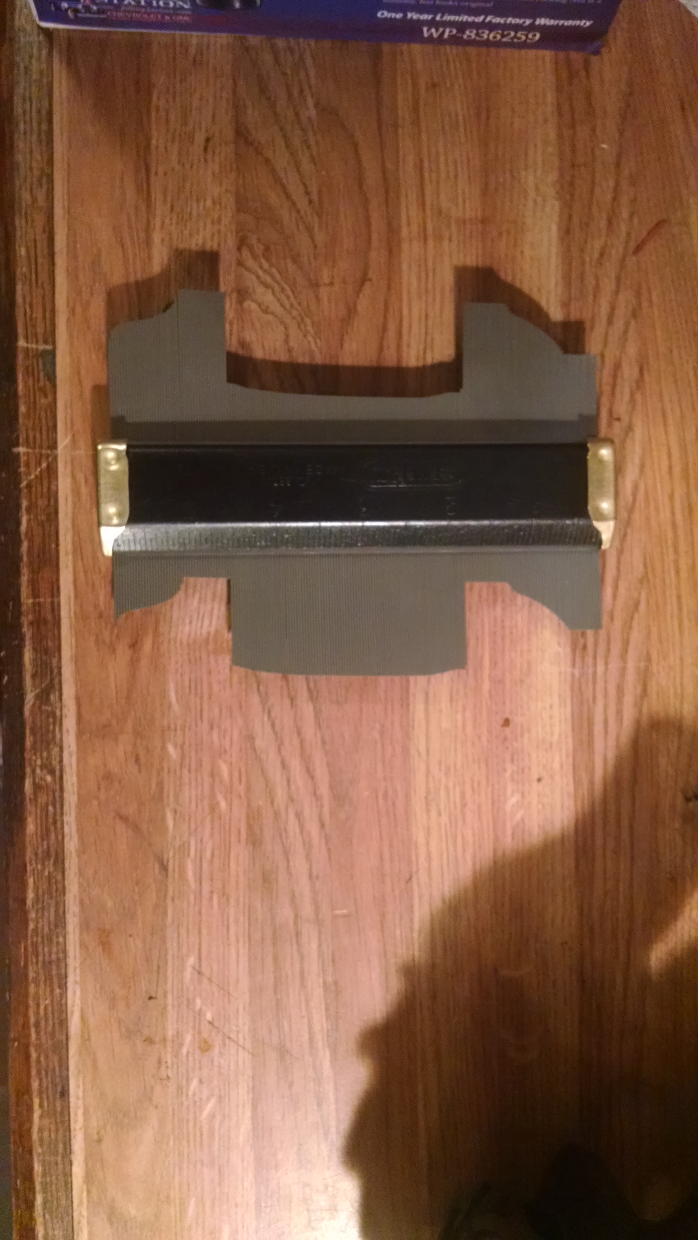
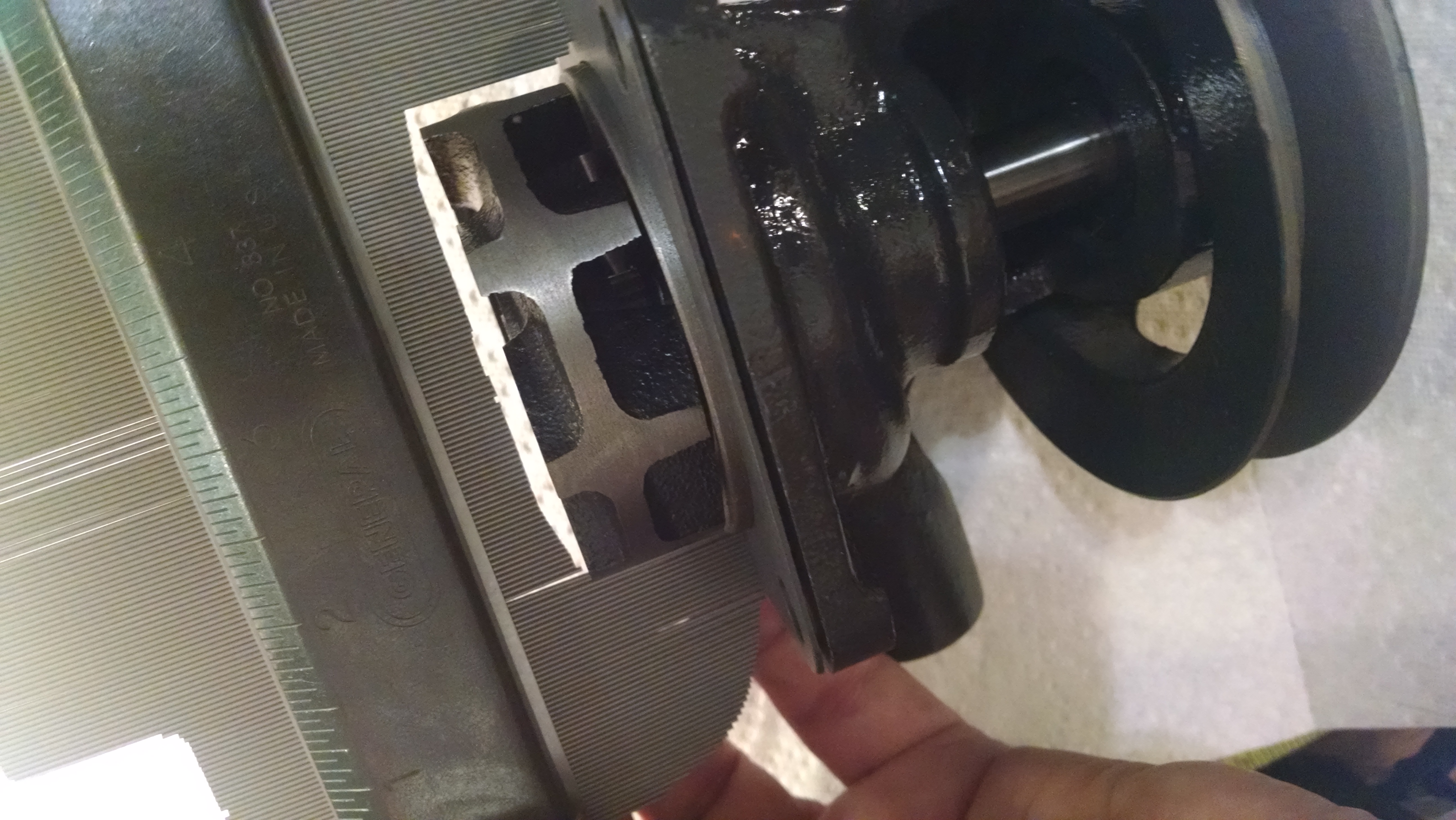
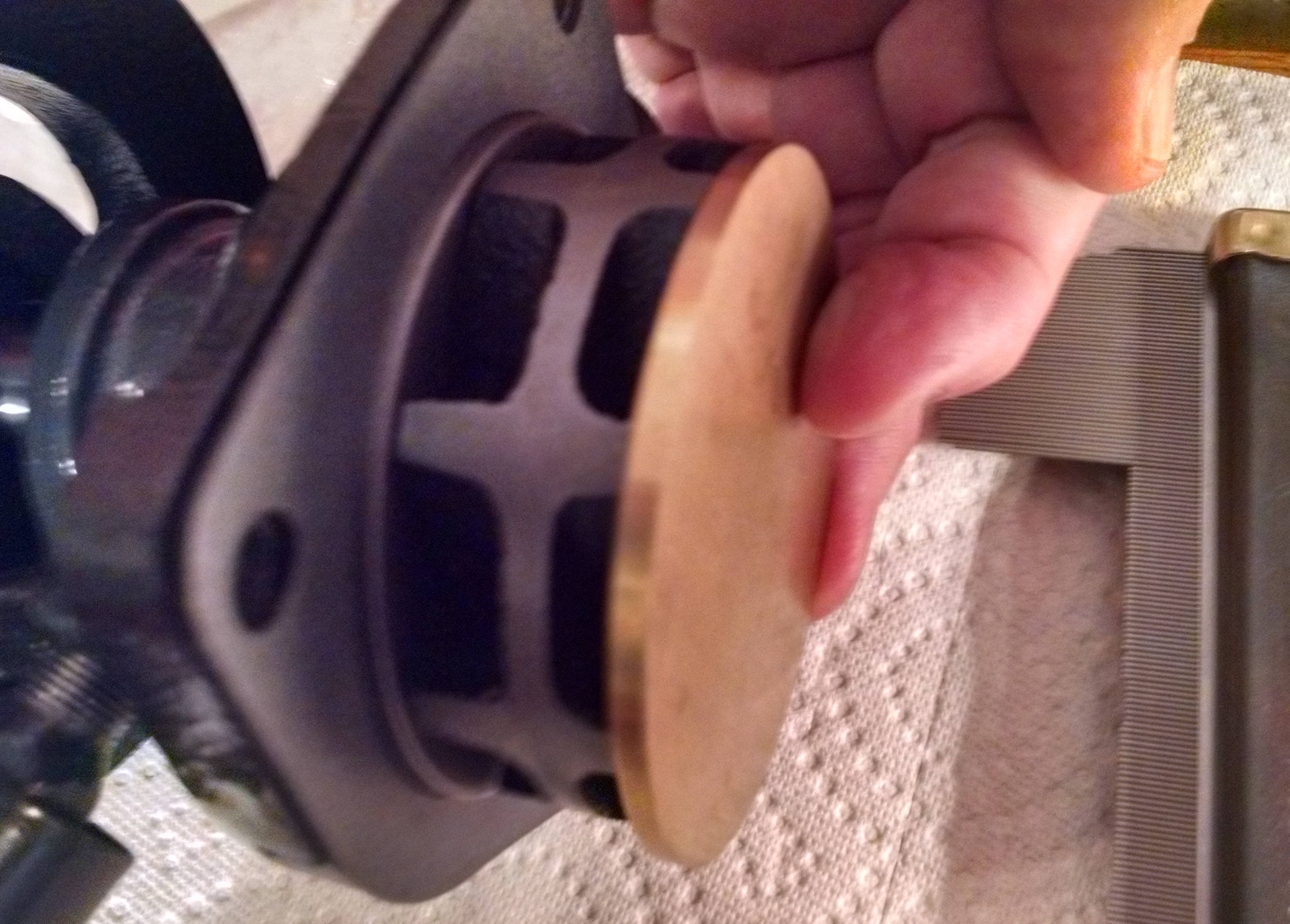
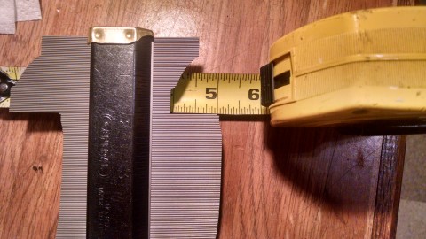
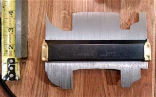
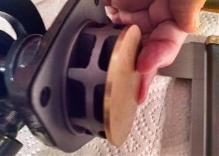
When I pressed it into the opening in the front of the engine block, the EXACT size and shape of the baffle plate became immediately apparent. |
When you look at the gauge, the inserted shape is on the bottom of the image above. The top of the tool is an exact replica of the actual opening. |
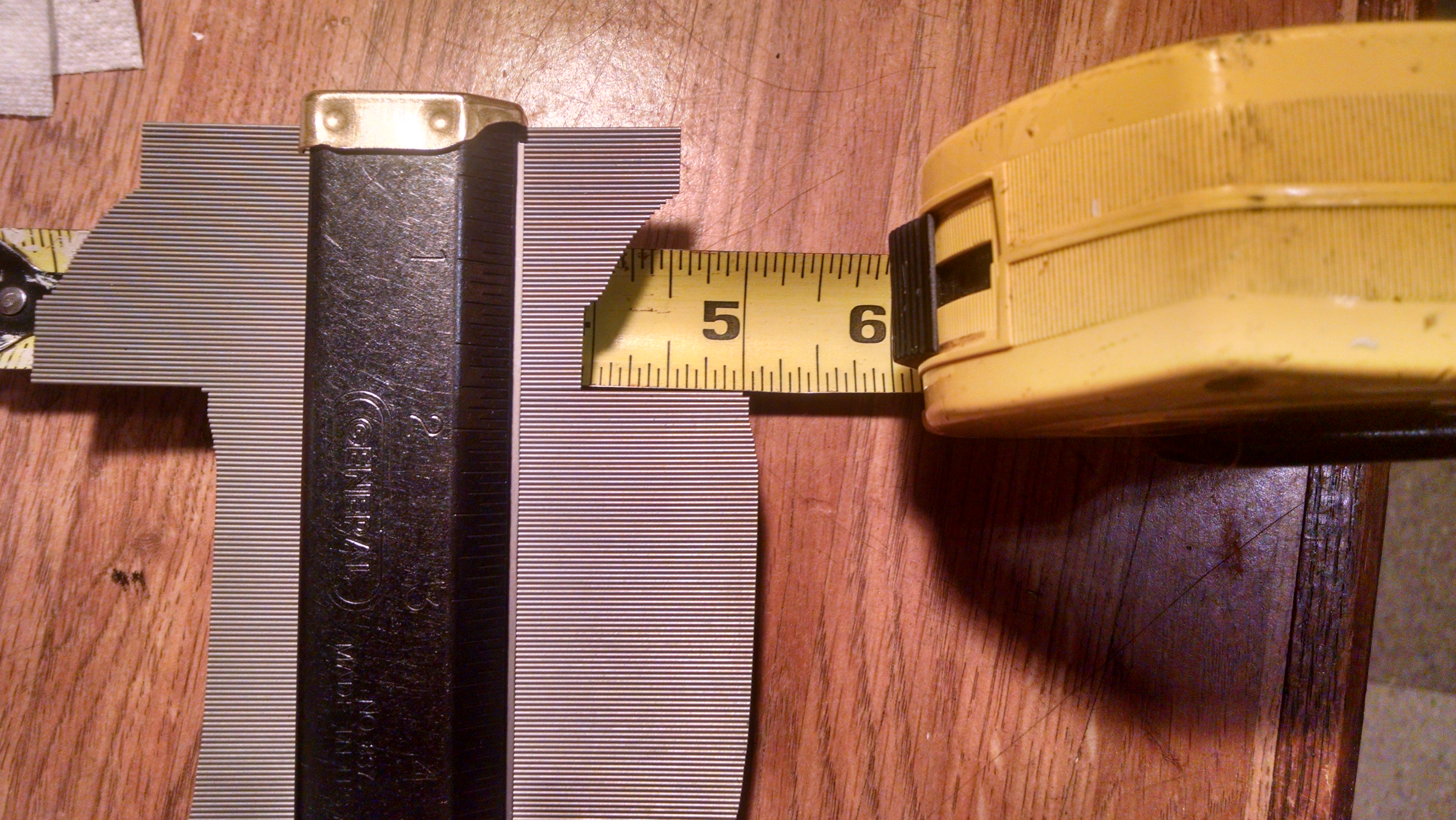
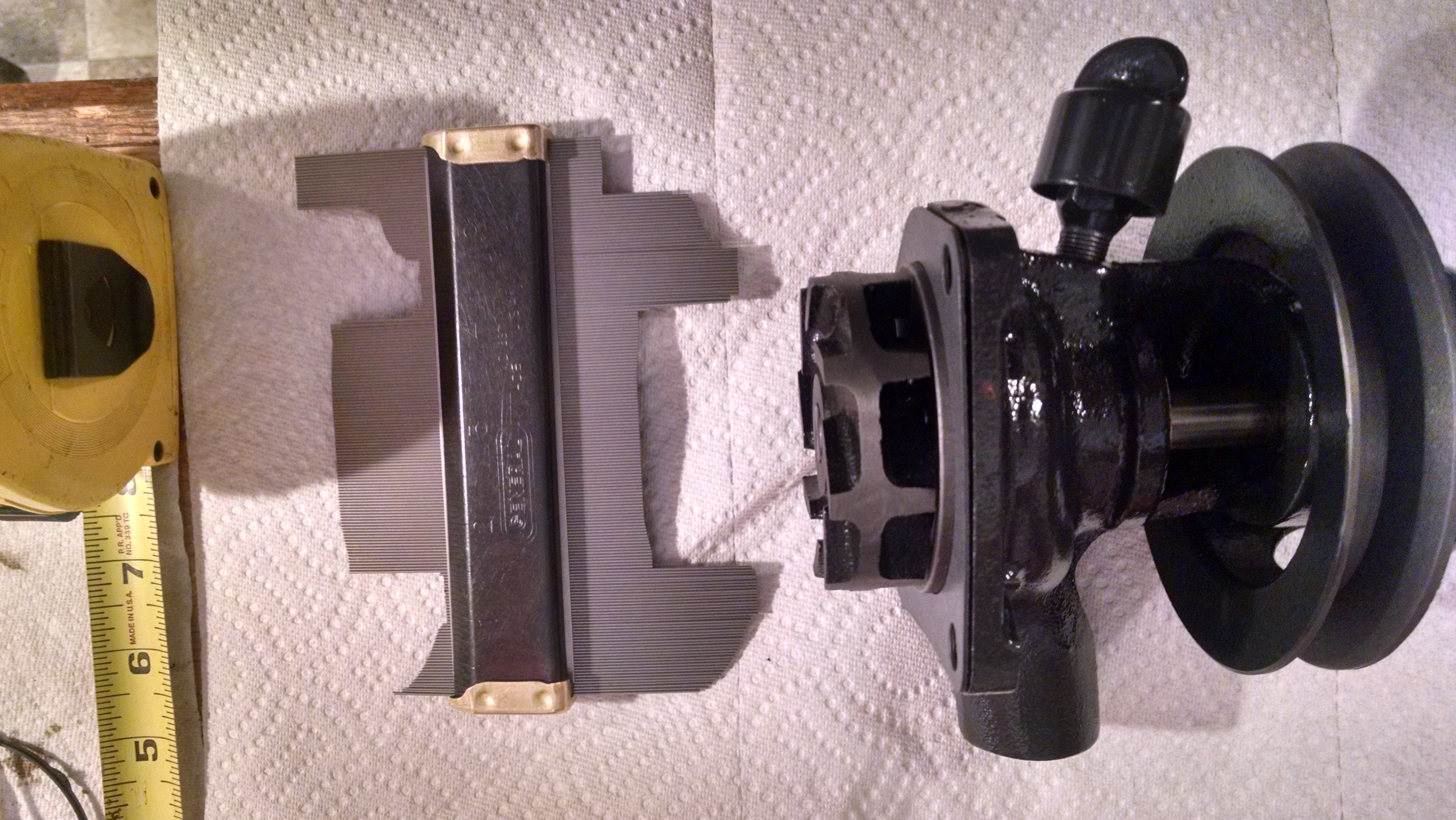
When I measured the tool impression, it was 1 1/16' deep.
This is a significant measurement since it is the actual depth from the machined face of the head to the baffle plate. The water pump is about 15/16" from the machined face to the outside of the impeller. So between these two measurements you can conclude that there is 2/16" of an inch gap. And when you add a gasket, the gap will become slightly larger still. |
|
|
|
I did it a second time and measured again. (Note: the photo has a slight offset so you may not see the same measurement.) |
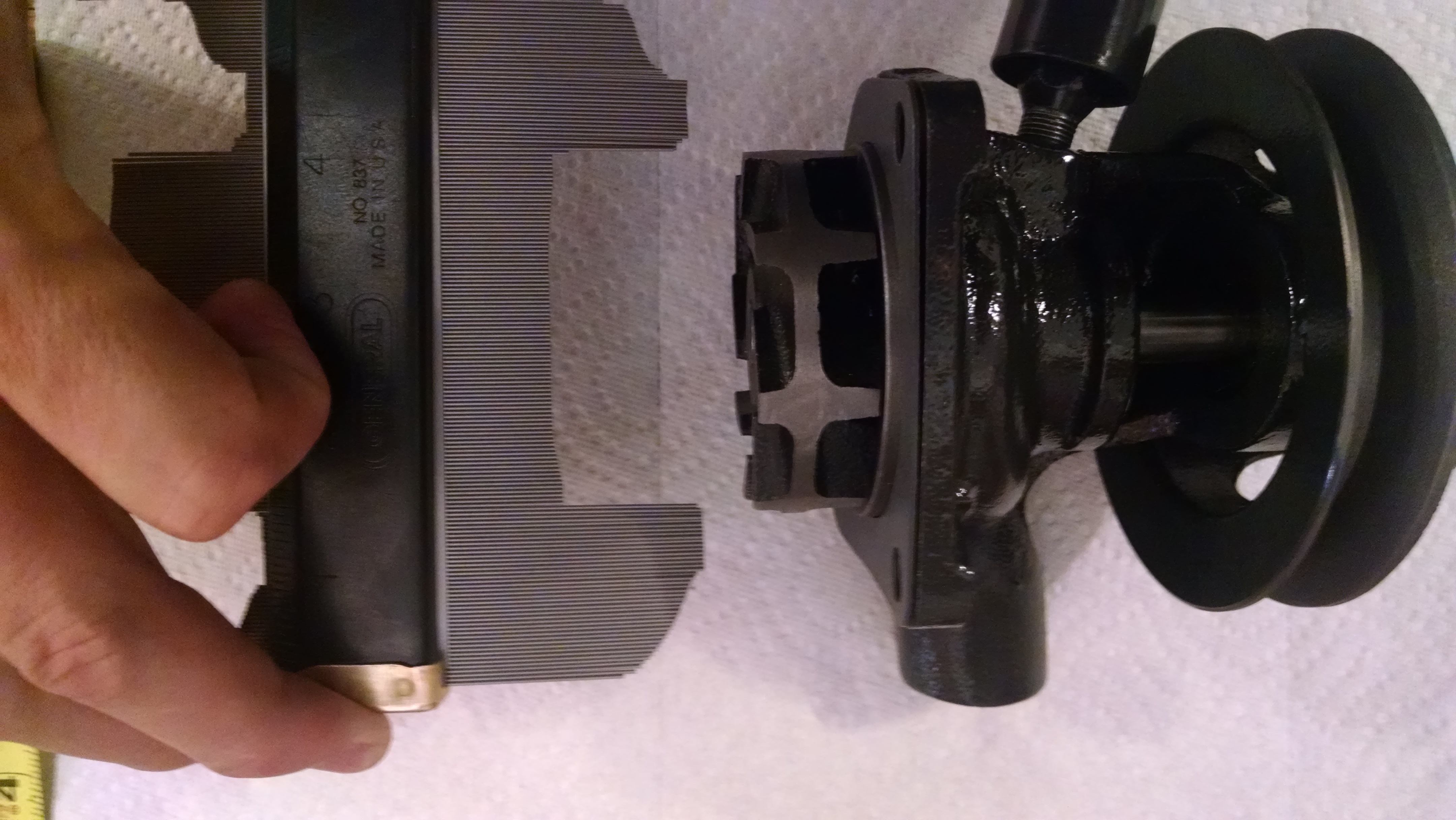
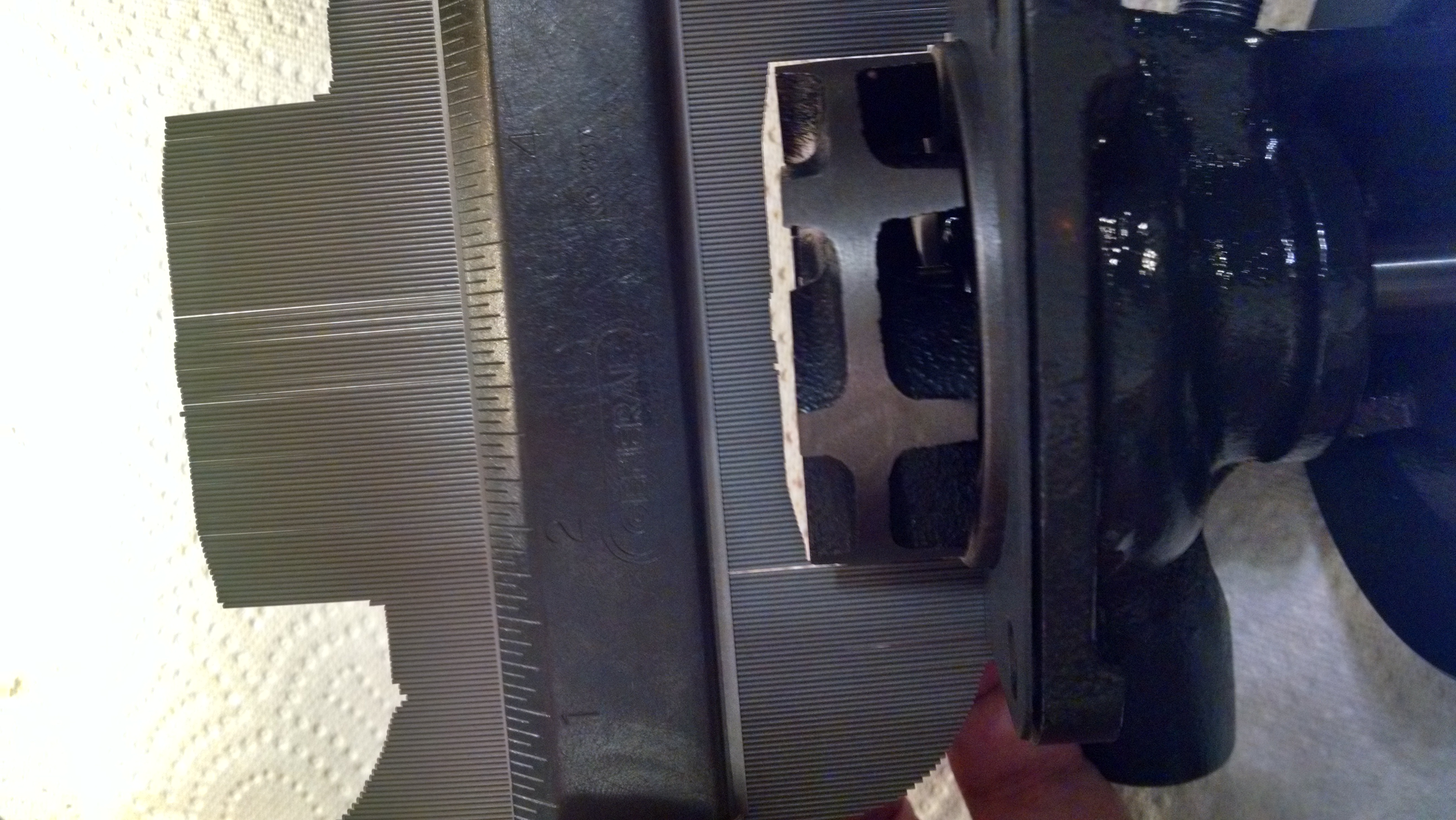
Holding it up to the pump, you can see the gap between the outer edge of the impeller and the depth marker. |
This is the are of concern for me. Is this too much? And I recognize that the gasket will make it a little larger yet. |
|
|
|
 |
The gap was just over 3/32".
Add the gasket to that and you get 4/32" which is 2/16" or 1/8".
Using my crude socket tool, I concluded it was about 3/16".
Using the gauge tool is more accurate and shows that the gap is actually slight smaller than my original findings.. |
|
|
|
|
| LAST METHOD FOR MEASURING IT |
|
|

Start by pressing the tool into the water pump housing in the block. |
It makes a "positive" and a "negative" impression of the opening. This time I'll use the "positive" indentations. |
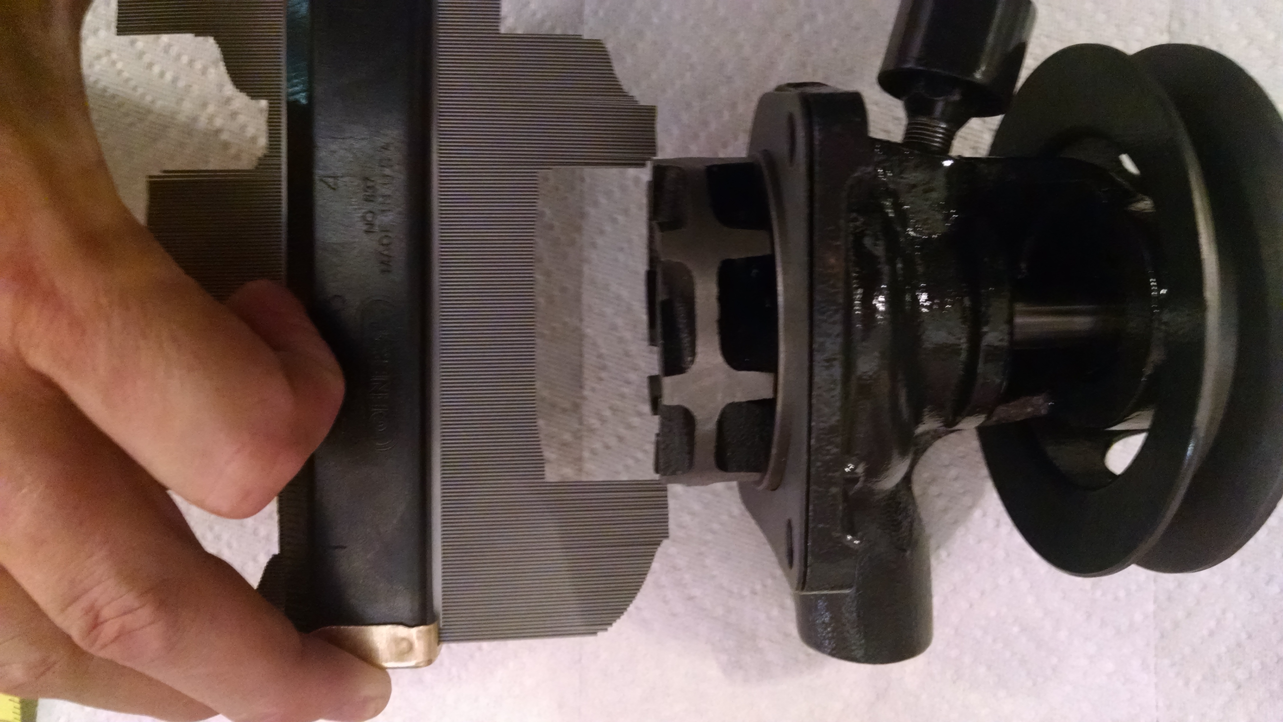
The method will be to hold the tool up against the pump. |
|
|
|
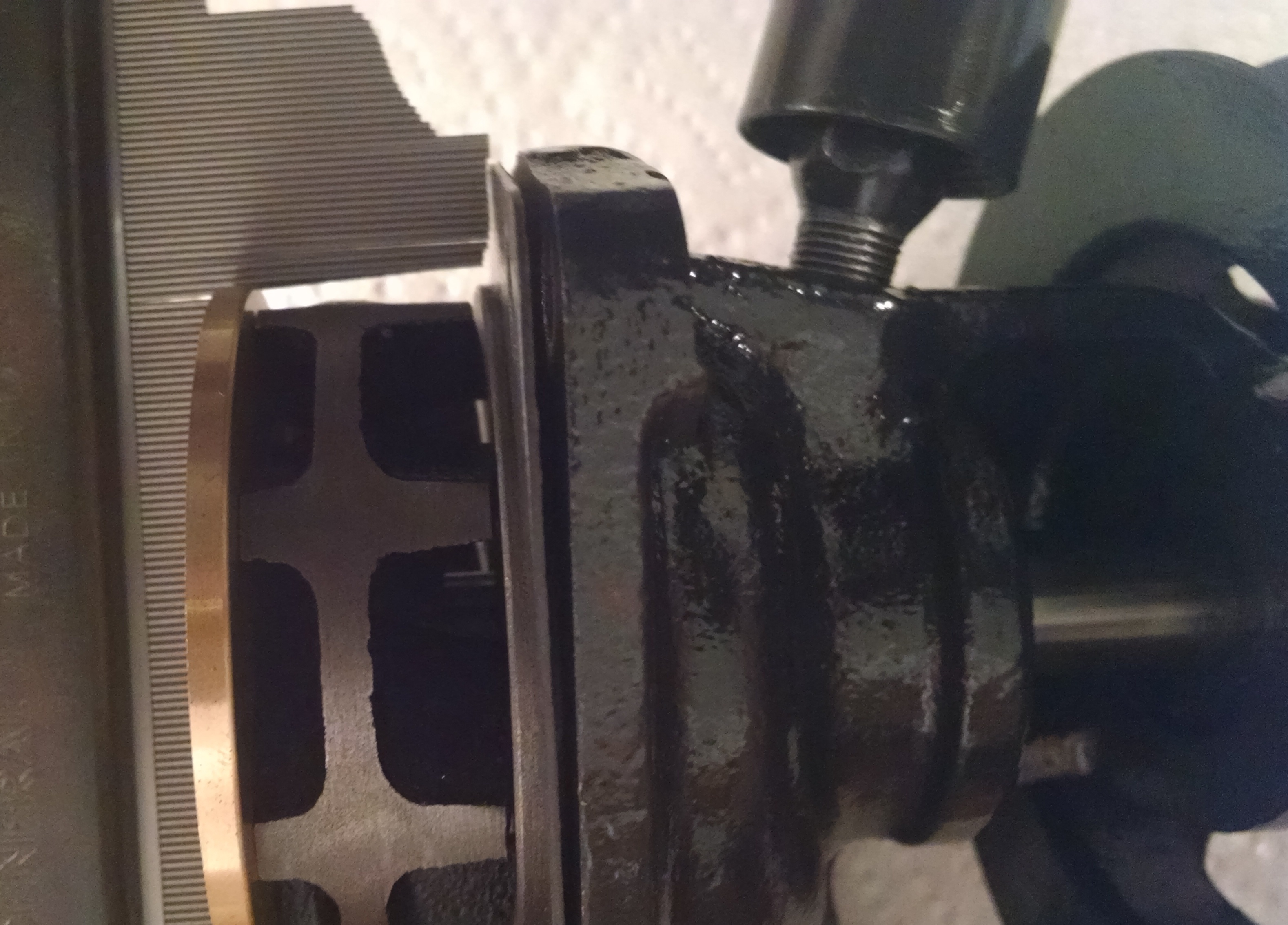
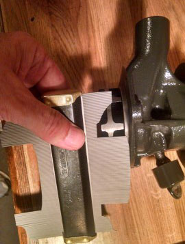
If you are careful, you can slip it right into place. |
You can see that there is sufficient room as you get closer. |
One in place against the machined surface of the mounting flange of the water pump, you can see the gap on all three sides. |
|
|
|
I took a lot of photos of this since a slight camera angle changes what you see. (Click on any photo to see a larger image.) |
The gap at the "edge" of the impeller is okay. Maybe 1/16". |
But the gap at the "end" of the impeller is what we are most interested in. You can see that it is small at the edges and wider at the middle. Exactly what my earlier socket-tool found. |
|
|
|
When I measured it, the ends were about 1/16" and the middle gap was about 3/16". |
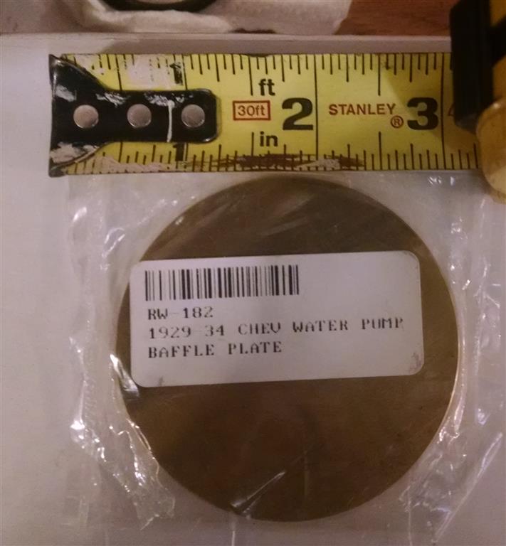
I placed the new baffle against the end for a measurement since it is exactly 2/16" thick. |
It fit okay in the middle, but the narrow clearance around the perimeter kept the tool from touching the surface of the pump - further proving that the current baffle is close around the circumference, but loose in the middle. |
|
|
|
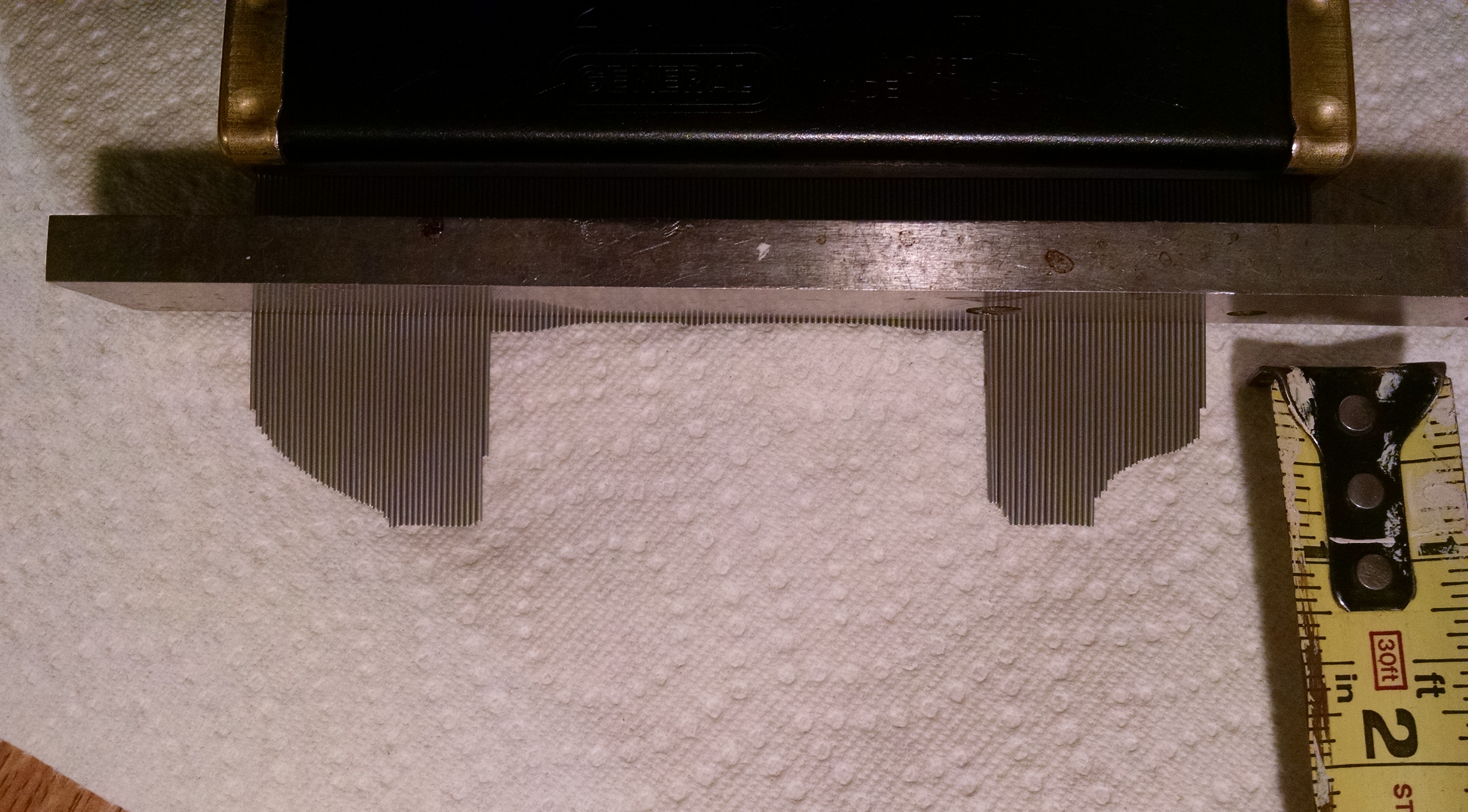
One final look a the contour tool with a straight edge laying on it. I can easily measure the different in the depth here. |
So, where I stand now. The existing (old) baffle is slightly indented in the middle. It appears to be about 3/16" deep. The edge of the baffle is about 1/16" deep. So the different is 2/16".
I have to say that I'm not as concerned about this now that I have accurate measurements. I'm sure that the pump is somewhat "over designed" for it's intended use. It will probably work just fine with this "sloppy" back plane against the impeller. |
The other thing that I'm taking into account, is that the new fin design on the replacement pump is different than the original. It is more "aggressive" and should easily move more water than the original fin design would.
So taking this into account, this should help offset the loss caused by the indentation of the baffle plate.
FINAL CONCLUSION:
I don't need to replace the Baffle Plate, this time. |
|
|
|
Let's install the new pump now. |
If you need to install a New Baffle Plate....

The ultimate solution to this issue is to replace the baffle plate. This is a fairly simple process once you get the old one removed. (See right.) These new "solid plates" are available from The Filling Station. |
Note: Removing the old baffle plate can end up being more complicated that it should be. To complete it without damaging anything else, you should remove the radiator so that you can get better access to the front of the engine, and the plate. You will probably need to "tap" the new one in place and you need the room to do that. Also, removing the old one may even require you to drill two holes and insert screws in order to get some leverage.
The way to remove the baffle is to punch a hole at the EDGE of it and then pry it out. They are mildly pressed into place. (CAUTION: If you hit the punch at the center of the baffle plate, then you could go through it and accidentally hit the block surrounding the number one cylinder. The casting is relatively thin here. If you crack it here, then you'll have a much larger problem than just the water pump.) The old plates are actually a fairly thin plate with edges facing inside. (More like a "cup" design.) The replacements are a thick, flat piece of bronze metal. The new ones will NEVER corrode through and are extremely unlikely to deform in the middle. |
|
|
|
VCCA MEMBERS: If you want to read an excellent description of the 1931 water pump and how to improve it, go to http://vcca.org/members and after you log in, go to the Resource Center, then G&D Magazine, then Articles-Archives. Search for "water pump Jackson". If you're not a member of the VCCA, then you might consider joining. They have over 1,000 pages of old technical articles online. (http://vcca.org). And at least 7 years of complete magazine issues online.
|